Infrared Scanning
Infrared Inspections on Electric Panels without Removing Covers: Can the Inspection be Completed Correctly?
ABSTRACT
There has existed in the past a misunderstanding that Infrared Thermography could be accomplished without the benefit of removing panel and/or dead front covers on electrical apparatus. This would be wonderful from the standpoint of logistics, manpower, and labor hours.
The basis behind this paper is to complete several electrical component inspections using infrared diagnosis with breaker cabinet covers on and off to determine if the scans can be successful by leaving the various covers in place. Before and after images were collected on several different location cabinets to determine the results. We have the proof to aid all thermographers in their decisions to leave covers in place, remove covers safely, or install IR windows. What will your decision be?
INTRODUCTION
As we all know, our cameras used in performing services in any application are not X-Ray devices that allow for “seeing” through solid surfaces and materials. We know that when temperature variations are visible to the camera on these types of scenarios, the actual problem area and source of the thermal energy is going to be exponentially higher at the source, and the camera is “seeing” only a portion of the total.
REAL WORLD EXAMPLES TAKEN DURING INFRARED INSPECTIONS
The following examples were taken on site during actual component inspections over the last year. We will give the necessary details of each component and show both infrared images prior to removing the cover and after removing the cover.
Our first two examples explore the possibility of doing proper IR thermography in breaker panels without removing the dead front cover to view the actual buss and load side lugs.
EXAMPLE #1
OPERATING PARAMETERS
- 20 Amp Square D Single Pole Breaker.
- Loaded 5.2 amps.
- 6% THDC.
- High emissivity target on the dead front cover due to its painted surface (around .94).
- Lower emissivity target at the line lug, but geometry and cavity allowed for an improvement in emissivity for a more accurate measurement of the problem (around .89).
- .785 Millivolt drop across contact.
- 10-12 degree C difference between the breaker body and problem spot at the line side, as heat was conducted to the line lug and was more predominant there as opposed to the load side. This would be masked if the dead front cover was not removed.
- Controlled environment in a college hallway, no forces or natural convective cooling, ambient temperature around 20 degrees C, no background radiation.
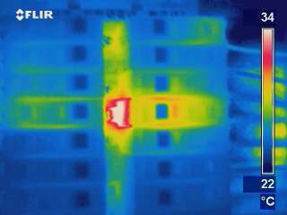
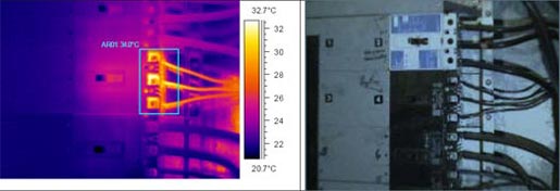
As you can see in Figure #1 prior to the removal of the dead front cover, there is an obvious load on the suspect breaker 4th down on the right.

The observed temperature is around 30 degrees C and within the manufacturer’s operating specifications. The temperature on the dead front cover is closer to 23 degrees C and not an apparent concern, right? One may simply deduce this is only load created energy on the breaker and bypass it during an inspection.
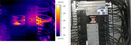
Once the cover is removed, a far worse issue is revealed in Figure #2.
- The problem area is centered on the line side connection.
- The actual problem temperature at this light load was approximately 39 degrees C.
- This is an error of nearly 9 degrees C.
- If the cover had not been removed, this more than likely would have been bypassed.
- Any addition of loads would increase the problem temperature exponentially.
EXAMPLE #2
- 60 Amp Square D Single Pole Breaker.
- Loaded 12.5 amps.
- 6% THDC.
- High emissivity target on the dead front cover due to its painted surface (around .94).
- Lower emissivity target at the line lug, but geometry and cavity allowed for an improvement in emissivity for a more accurate measurement of the problem (around .90).
- .289 Millivolt drop across contact.
- 15-17 degree C difference between the breaker body and problem spot at the line side as heat was conducted to the line lug with less thermal resistance, and was more predominant there as opposed to the load side. This would be masked if the dead front cover was not removed.
- Dusty, warmer environment in a industrial laundering facility hallway, no forces or natural convective cooling effects, ambient temperature around 23 degrees C, minimal background radiation effects on the target from industrial dryers.
- Again, a lightly loaded breaker compared to the rating.
- Around 32 degrees C on the breaker case and well within the manufacturer’s specifications for rise over ambient.
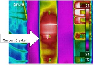
- No apparent “deficiency” was observed relating to temperature on the dead front cover, and it was operating at around 22 degrees C, which can be seen by viewing the thermal image in Figure #3.
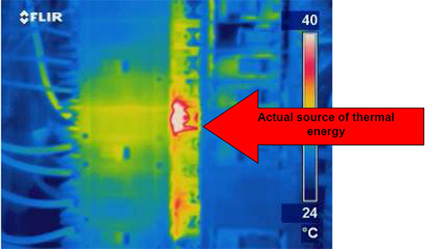
- But when the cover is removed, a different story is uncovered, as is shown in Figure #4.
- As seen below in Figure #4, the actual problem area again is the bus connection to the breaker.
- But unlike the 22 degrees C observed on the dead front cover, the problem temperature is now running closer to 43 degrees C.
- This is an error of nearly 22 degrees C.
Again, with load demand being light at the time of the survey, increases and the consequences thereof must be considered. This is another clear example of how temperature errors by improper procedure of the technology for the electrical application can occur.
The next part of this discussion will be used to determine whether or not cabinet doors themselves need to be removed to perform a satisfactory infrared survey.
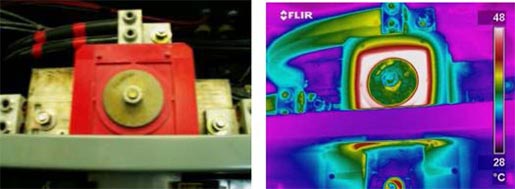
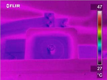
Example #3
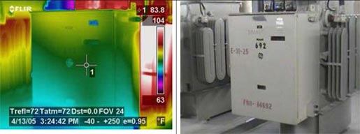
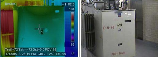
Consider the infrared and visual images shown in Figures #5 and #6. Both show the 480V buss cabinet and connections associated with a 13.2KV to 480V step down transformer. The cabinet in Figure #5 is running approximately 2°F warmer and shows considerable heat towards the top of the cabinet due to convective gains. This would seem to point to a potential issue in the 692 cabinet and no issue in the 691 cabinet. However, upon removal of each of the covers by approved safety measures, we scan with the IR camera again and find the images to be opposite of what we originally thought.
The cause of the heat on the warmer 692 cabinet was load related. Cabinet 691 actually had an anomaly that would have gone undetected by not properly removing the cover during the inspection. Also, the fact that this anomaly was found at approximately 10% of the system’s rated load shows how a fairly important problem could have been overlooked. Once the load is increased, the heat generated by the fault will increase exponentially. Our calculations would have this rise increase to approximately 110°C when the transformer was under 80% load.
EXAMPLE #4
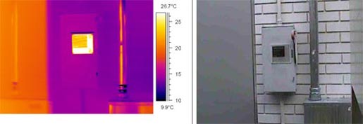
Our next example is of a 480V main disconnect on the outside of a customer’s business. As I pointed out earlier in this paper, we took IR images from the outside of the cabinet prior to opening it. Figure #9 shows both the visible and IR images of the cabinet.
No issues were noted from the outside inspection. We then opened the cabinet using approved safety procedures and scanned the internal fused disconnect to look for suspicious hot spots. The problem would have been missed! Refer to Figure #10 for an infrared image clearly showing a problem on the C phase incoming connection. We needed to open this cover in order to identify it. The C-phase fuse was in need of replacement, so the recommended action was to replace all three with new fuses.
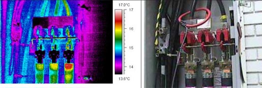
Our next example in this paper is a medium voltage breaker with the dead front cover still in place. We have a minor temperature rise of about 3°C shown on Breaker #4 (see Figure #11).
This infrared image shows that the breaker is a little warm, but not warm enough to warrant further investigation, right? We pulled the dead front cover, again following all safety regulations, to see if there was anything worth reporting to our important customer.
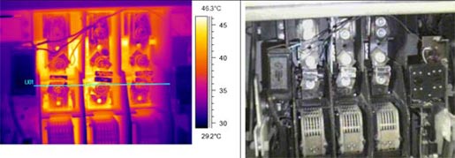
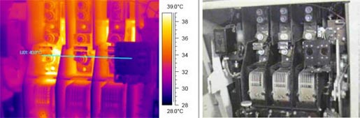
This image (Figure #12) shows that the contact temperature was about 10°C higher than what was shown on the surface of the breaker. Also, NO anomaly was shown on the outside of the cover itself. We decided to remove the buss side cover to investigate the other side.
With the load side cover removed (Figure #13), we noted a slight rise on the middle phase connection. The “issue” on the bottom phase buss was a reflection, but the connection was a true hot spot. It was at this point that we used our other tools available to get a voltage drop across the different connections and breaker contacts to determine where our issue was emanating from. With over a .275-millivolt drop across the B-phase contact of the breaker itself, we determined that Breaker #4 was in need of replacement.
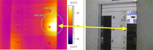
In one final example at a Medical Treatment Center in Fairbanks, Alaska, a Square D I-Line Panel rated at 800 amps was our target. Prior to performing any maintenance on the equipment, the customary Ultrasonic Airborne Safety Scan was performed and no anomalies were detected. As an additive safety precaution, we also conducted a brief IR scan with the camera on the exterior of the panel. The Digital and Infrared images are illustrated below in Figure #14:
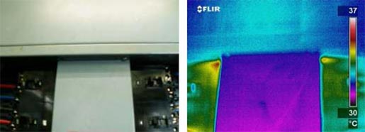
As indicated in the images, there are no alarming thermal patterns on either the dead front cover (around 30 degrees C) or the main lug access cover. Some indications at the top corner of the dead front do illustrate some energy, but this could be merely load related heating effects. Once the dead front cover is removed, it is a bit more apparent that there is some type of heating occurring near the top of the panel, which is indicated in Figure #15 below:
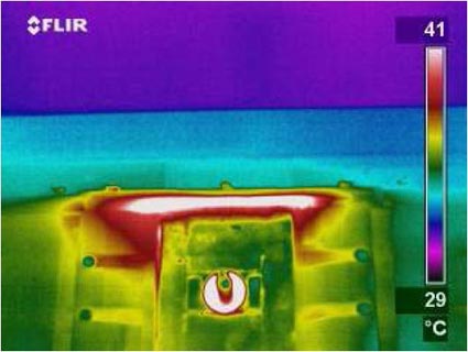
The image above certainly illustrates that there is something suspect within the panel (now the temperature is around 42 degrees C); however, it is still not conclusive as to the source or the severity of the condition contributing to the thermal emission we are observing. Once the top main lug access cover is removed for inspection, it becomes reasonably clear that there is a deficiency on the main lug connections illustrated in Figure #16, but where and which one(s)?
Even without the implementation of complete analysis procedures, it is evident that the problem is centered on the main lug assembly, and that the problem temperature is actually 53 degrees C. This is nearly a 22 degree C error in temperature with the covers on and with them removed. Additionally, terminations are rated at 65 degrees C absolute, and this 800 Amp panel had balanced loads of 450-460 amps. This represents only 50% of its rated capacity, and not all of the customer’s loads were in use at the time of the visit. Once these additional loads are added, the problem temperature will then begin to increase exponentially, and it won’t be long before it will exceed the 65 degrees C rating of the lugs. This will cause them to rapidly deteriorate and ultimately fail, possibly causing a fire and damage to other components.
Once this evidence was presented to the customer immediately while on site, authorization to perform the repairs was secured for 12:00 AM that evening. The panel was deenergized, the main lugs were disassembled, inspected, cleaned with emery cloth, new hardware was used to reinstall it, the toggle bolt was torqued to Square D’s specifications, and the panel was returned to service.
At this point the job is completed, right? Wrong! We must ALWAYS return to verify any repairs we perform, particularly on agreements where they are guaranteed, using the IR camera to provide an illustration of how effective repairs were. In this case, you can see below in Figure #17 that they were extremely successful when returned to service. Under the same operating conditions, the “problem” temperature was reduced by nearly 25 degrees C, and is well within acceptable operating parameters.
SUMMARY:
In today’s world, the mentality and “buzzword” is lean manufacturing and reduced maintenance costs. Competition throughout the industry demands that we must all do more with fewer resources. This should not mean that in the interest of cost savings, shortcuts should be taken that can cause misjudgments which may contribute to downtime or equipment failure.
In the examples above, there are no doubts that problems that existed on line side connections. Analysis, including voltage drop measurements, confirmed that due to resistance issues, thermal energy was being created and radiated. Although there was conduction noted on the breaker cases, it most likely would not be considered to be abnormal, deficient, or in failure stage.
The Square D I-Line panel is an excellent illustration of the types of critical temperature errors that may be realized while performing services if we do not safely take that necessary step of removing ALL covers to have the line of sight to the target. For one to identify and quantify an anomaly on the exterior of an electrical enclosure, the severity of the problem and the amount of thermal radiation needed internally to be visible to the camera would be exponentially higher and near catastrophic failure. In this case, one would not want to attempt to open the enclosure while it was energized, and a shutdown would be the prudent course of action to correct the deficiency.
To be accurate in our analysis and identification of anomalies directly relates to our credibility with our customers. For this to be accomplished, we must follow established procedures each and every time we apply the technology. This becomes a function of the application and discipline we are practicing, along with the fundamental knowledge of the equipment we are performing services on.
It is an elementary requirement and an industry-accepted standard that to effectively perform infrared services on energized electrical equipment, it must be under normal load and operating conditions. Normal, admittedly, is defined as having the covers and dead fronts installed. However, from a maintenance and service standpoint, accuracy and precision must be the focus of our objectives, and this can only be achieved by the safe removal, each and every time, of both panel and dead front covers on electrical equipment. This is imperative to ensure that our preventive maintenance programs do not overlook potentially critical issues and cause customers to experience unscheduled outages and equipment damage.
REFERENCES
Lyon, Bernard R. Jr.; Orlove Gary L. and Peters Donna L.; “The relationship between current load and temperature for quasi-steady state and transient conditions”; pp. 62-70; Proc. Thermosense XXII; SPIE Vol. 4020; April, 2000


